
Assessment protocol for nozzle loads on pressure vessels
In practice engineers often struggle with the design of pressure vessels in early stages of a project, when the piping loads exerted on the nozzle by the connected piping are yet unknown.
The prevailing assumption is that external loads require by definition additional reinforcement of the nozzle on top of the strength required to withstand the internal pressure. Hereby on one should think of applying reinforcing pads or increasing the size of repads or even a thicker vessel wall to compensate for unknown external loads.
The vessel design engineer may have at his disposal a set of standard nozzle loads. However, the background of these loads may be unknown and, when used in conjunction with the internal pressure, often leads to additional reinforcement of the nozzle.
In [1] Walther Stikvoort poses the argument that extra reinforcement rarely proves necessary as the recognized design code or standard will already provide for a reasonable amount of piping imposed loading ability.
To this end the nozzle loading ability is determined with the nozzle assessment protocol as described below. Characteristic of the approach is to have the limit values of the individually permissible nozzle loads available at an early stage. The procedure to be followed requires a joint contribution from both the vessel design engineer and the piping stress analyst.
Assessment protocol
The following step-by-step approach explains the roles of the vessel design engineer (A) and the piping stress analyst (B).
A. Vessel design engineer
- Step 1: The vessel design conforms to the applicable code or standard considering only internal design pressure.
- Step 2: The allowable individual loads for each process nozzle are calculated, including the flange.
- Step 3: The vendor/vessel manufacturer furnishes the individual allowable forces and moments for each process nozzle-vessel intersection, as well as for the nozzle flange, in a tabular form on the appropriate drawing of the relevant equipment item. Normally this should be done twice: in the preliminary bid phase, and in the final mechanical design phase.
- Step 4: The information compiled in Step 3 must be transferred to the piping stress analyst.
B. Piping stress analyst
The starting point for the piping stress analyst is the compliance of the connected piping with the applicable design code:
- Step 5: Determine exerted nozzle loads (piping reactions) using an accepted software program.
- Step 6: Prepare a summary of piping reactions for the relevant process nozzles.
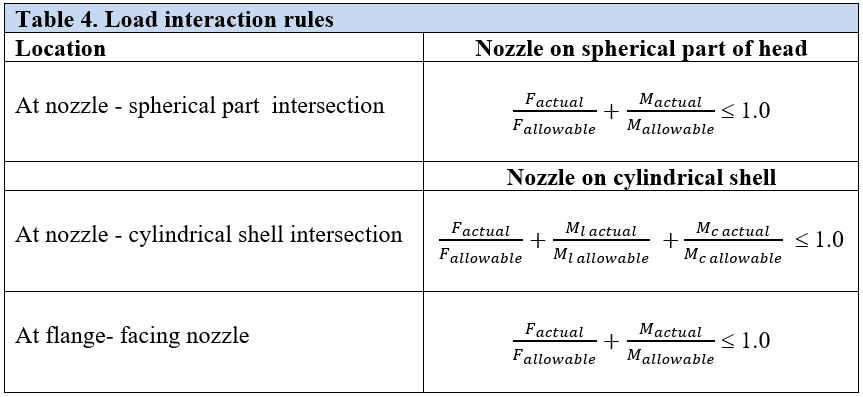
- Step 7: Provide load interaction checks at each process nozzle-vessel intersection and flange connection. In practice, this often means a joint effort of the vessel design engineer and the piping stress analyst. Both disciplines must be convinced that simultaneous action of internal pressure and external loads are acceptable.
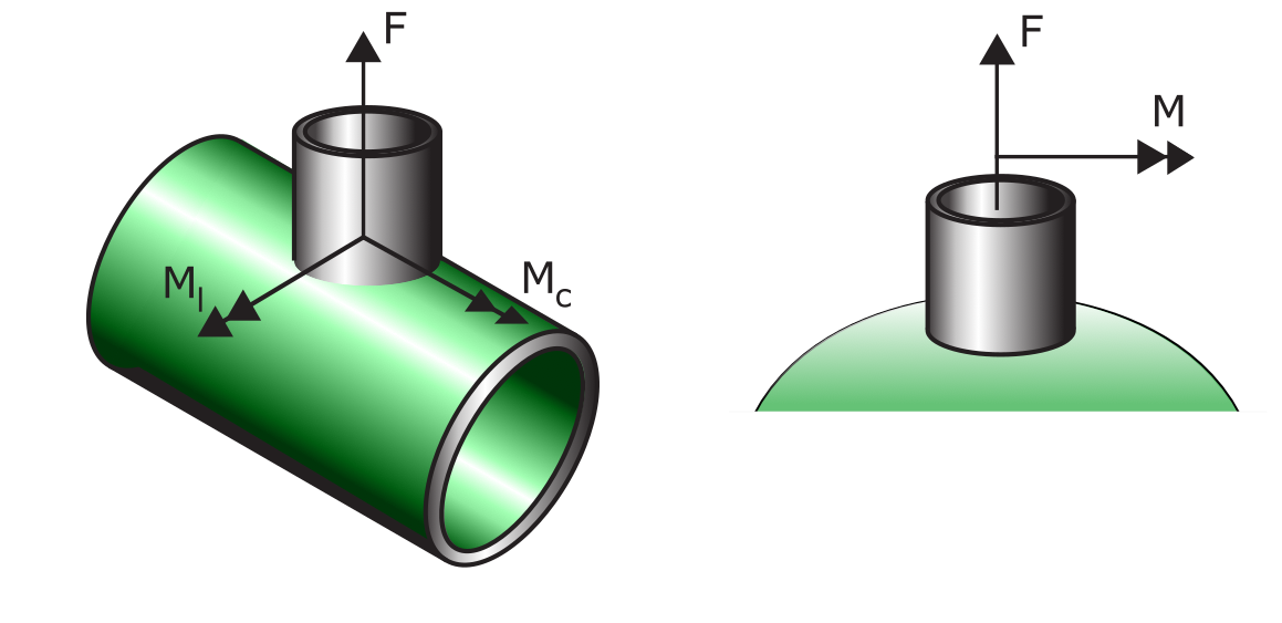
Linear load interaction rules that apply are shown in Table 4. The result of the load interaction rules must be recorded in the piping stress report.
Note: In cases where the piping reactions are not permissible, re-routing of the piping system or rearrangement of the pipe supports should be considered. Often, discounting the nozzle flexibility in the pipe stress analysis results in a drastic reduction of the piping reactions—this is certainly the case with relatively thin-walled pressure vessels where the nozzles are not equipped with reinforcing pads.
The pressure vessel nozzle is considered acceptable if the load interaction conditions are met. It is the author’s view that the nozzle design according to the recognized codes/standards will provide a reasonable amount of piping-imposed loading ability. See [1] for a worked example that demonstrates the approach.
[1] W. Stikvoort, Assessment protocol for nozzle loads on pressure vessels, Hydrocarbon Processing Magazine, Hydrocarbon Processing Magazine, May 2022.