
Dimensioning a custom heat exchanger flange can be done quite quickly using a number of simple rules. Starting with the internal diameter B the flange dimensions can be determined step by step. The end result is a feasible flange with dimensions that can be used to do a stress analysis with, for example, the P3 Engineering VES-software.
This blog is a condensed version of the full paper that is available here. Equation numbers in the text below refer to the original formulas in the full paper.
1. Design data
Start with the following design data which should be known in advance:
- The design conditions
- The design pressure Pd
- The design temperature Td
- The corrosion allowance Ca
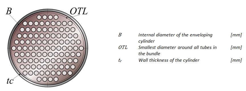
- The Outer Tube Limit OTL which is the smallest diameter that includes all tubes in the bundle.
- The bolt dimensions
- Bolt diameter db: Start with ¾” or M20
- Total bolt area Ab = number of bolts (nb) × bolt area per bolt (Ak)
- Total maximum bolt load Fnb = permissible tension of the bolt material (fba)× Ab
- The compression factor m of the gasket, with m=2 for camprofile gaskets, m=3 for spiral wound gaskets, m=5.5 for steel flat rings
For a leak-free flange connection, the maximum bolt load Fnb must be sufficient to apply the required gasket pressure.
2. Cylinder dimensions
The flange dimensions are constructed from the internal diameter B (see Figure 1) and are determined from the inside out.
Afterwards, when the external flange diameter A has been calculated, the gasket dimensions can also be determined.
First the internal diameter B is calculated:
(10) B ≥ OTL + 12 mm
The internal diameter B may have to be larger depending on the function or construction of the heat exchanger. For example for a boiler type heat exchanger or when space is required for sliding strips.
Secondly, the required wall thickness tcr of the connecting cylinder is calculated using the formulas of ASME VIII Division 1 - Appendix 1 and the material properties from ASME II - Part D:
(11) tcr = Pd × R0 / (S × Ei + 0.4Pd)
Where R0 is the external radius of the cylinder, S is the permissible stress of the material, and Ei is the weld factor of the longitudinal seam of the cylinder. See Appendix A of the full paper for tabulated values of tcr as a function of design pressure Pd and design temperature Td.
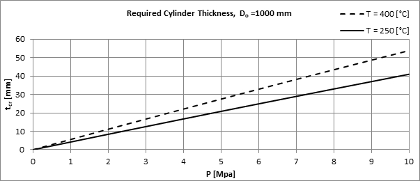
For diameters other than 1000mm see formula (12) in the full paper.
In addition a manufacturing tolerance ttol on the wall thickness tc must be taken into account in case a standard pipe is used. The tolerance for pipes according to ASME B36.10M and ASME B36.19M is:
(13) Ttol= 12.5%
For pipes made of materials from the European standards EN 10216 and EN 10217 there are different tolerances depending on the type of material, carbon steel or stainless steel, the diameter and the wall thickness.
3. Flange dimensions
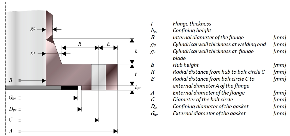
Take the hub thickness at the welding end to be equal to the wall thickness tc of the cylinder:
(14) g0 = tc
The hub has a minimum height that depends on the machines and tools used. We choose a minimum hub height of 15 mm:
(15) hmin = 15 mm
Increase the minimum hub height if more space is needed around the hub as a result of the manufacturing process.
The height h of the hub also depends on the thickness g0 at the welding end. This dependency is given by the hub height coefficient:
(17) h = Chh × g0 ≥ hmin , where Chh is the hub height coefficient which is taken as 2.
The thickness g1 of the hub on the flange blade is:
(19) g1 = (h / Chs ) + g0 where Chs = 3 for a conical hub slope.
The external diameter Dh of the hub is then calculated as follows:
(20) Dh = B + 2 × g1
Depending on the application or manufacturing method, different values for hmin, Chh, and Chs can be chosen. Please make sure that the slope of the hub still meets the requirements of the selected flange calculation norm. The slope coefficient Chs should not be chosen too small.
Appendix B (Bolt Dimensions) of the full paper contains the minimum values for radial flange sizes R and E. These minimum sizes ensure that there is enough space for mounting tools and that the nuts do not protrude beyond the flange.
The radial distance from the hub to the bolt circle has to satisfy the following constraint:
(21) R ≥ SHmin
The size SHmin is based on a socket wrench or a torque wrench. Other values are available for hydraulic tightening equipment that depends on the diameter of the hydraulic head. Each tool supplier has its own datasheet with minimum radial distances for R and E.
Also a minimum value applies for the radial distance E from bolt circle C to the external diameter of the flange blade A:
(22) E ≥ SEmin
Now the diameter of the bolt circle C can be calculated as follows:
(23) C = Dh + 2 × R
And for the external diameter A of the flange blade the following rule applies:
(24) A = C + 2 × E
Because the minimum radial distance E increases for larger bolt diameters, the external diameter A will also increase when choosing a larger bolt diameter db.
The exact flange thickness cannot yet be determined, because for a norm calculation all dimensions of the flange must first be known. Therefore an estimate for the flange thickness t is used as a starting point. The estimate is a function of the previously determined cylinder thickness tc and a thickness coefficient Cft. The initial estimate for the flange thickness is calculated as follows:
(26) t = Cft × tc, where Cft ∈ [5,6,7]
With an increasing cylinder thickness tc, which depends on the design pressure Pd, the estimated flange thickness t will increase proportionally. The final norm calculation will show whether this flange thickness t is sufficient. If this is not the case, the optimum flange thickness must be found in an iterative way. Different flange norms will result in a different flange thickness.
4. Bolt dimensions
To determine the bolt dimensions standard tables are used where the bolt dimensions and fitting dimensions are given as a function of the bolt diameter. See Section Appendix B (Bolt Dimensions) of the full paper for more details.
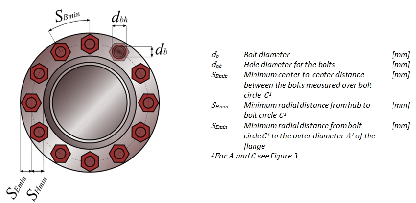
The following rules apply to the diameter of the bolt hole (26):
dbh ≥ db + 2.5 mm for M12
dbh ≥ db + 3.0 mm for 3/4"
…
dbh ≥ db + 10 mm for M56
where db is the nominal bolt diameter.
A smaller bolt hole diameter dbh is possible if the misalignment of the flange is limited during installation. In this case the following applies to all bolt holes:
(29) dbh ≥ db + 3.0 mm
The maximum distance between the bolts Sbmax can be determined in two ways. The first way is according to TEMA RCB-11.23- Load Concentration Factor in which Sbmax is determined as follows:
(31) Sbmax = 2db + 6t / (m+0.5)
The second way is to determine the maximum distance Sbmax between the bolts using ASME VIII Division 1 - Appendix 2:
(32) Sbmax = 2db + t
Limiting the distance between the bolts should prevent the seal from leaking. If the bolts are too far apart, there may not be sufficient gasket pressure in the area between the bolts. Leakage may occur in this area. If the bolt distance is still greater, the calculated flange moment in the norm calculation must be increased by a factor of CMb:
(33) CMb= √(Sb/Sbmax ) ≥ 1.0
The minimum distance between the bolts is determined with the tables in Appendix B (Bolt Dimensions) of the full paper.
The minimum number of bolts nbmin can now be determined with:
(34) nbmin = π × C/Sbmax
Similarly the maximum number of bolts can be determined with:
(35) nbmax = π × C/Sbmin
Finally the arithmetic mean is used to estimate the required number of bolts n'b:
(36) nb ≥ n’b = (nbmin + nbmax )/2, where nb ∈ [4,8,12,…]
The number of bolts nb must be a multiple of 4. For nb choose the next multiple of 4 bigger or equal to n’b.
The actual number of bolts nb in the flange design can only be determined using a norm calculation such as ASME VIII Division 1 - Appendix 2 which will show if there are enough bolts to keep the gasket closed.
5. Gasket dimensions
When designing a flange for a heat exchanger, a narrow gasket is assumed to lie entirely within the bolt circle. In addition, there is a confining diameter Dgc within which the gasket lies.
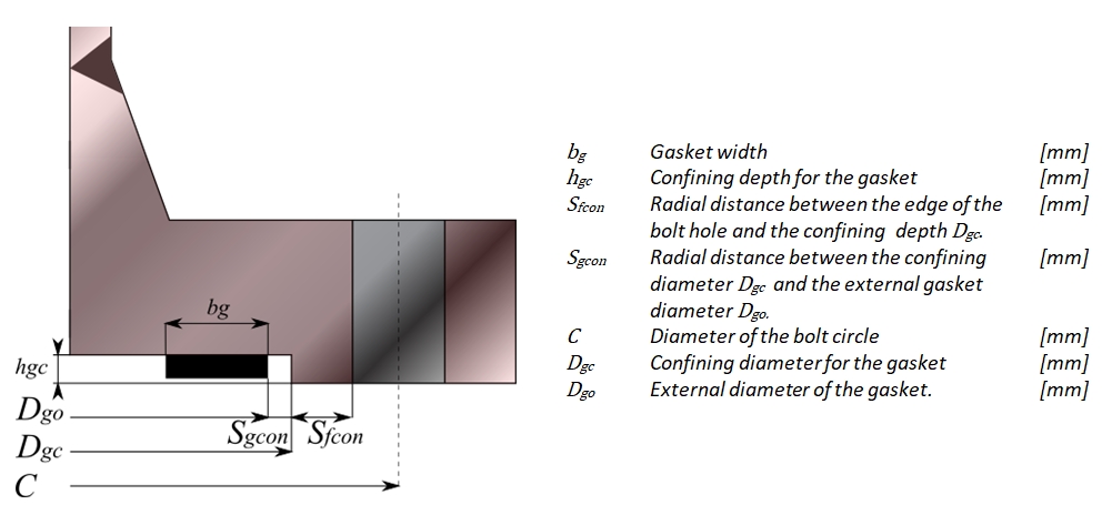
The minimum radial distance Sfcon from the edge of the bolt hole to the gasket confining diameter is at least equal to 6 mm:
(37) Sfcon = 6 mm
For large flange diameters, the value for Sfcon can be selected larger. Particularly for high design pressures, it can be advantageous to keep the gasket diameter as small as possible. This reduces the internal pressure surface of the flange. In that case Sfcon must be selected in such a way that the internal gasket diameter is close to the internal diameter of the flange.
The following formula applies to the confining diameter Dgc of the gasket:
(38) Dgc = C – dbh - 2×Sfcon
The confining depth hgc for the gasket is at least 6 mm and must be greater than the gasket thickness.
The minimum radial distance Sgcon between the confining diameter Dgc and the external diameter of the gasket is equal to 3 mm. This can be used to calculate the external diameter Dgo of the gasket:
(41) Dgo = Dgc - 2×Sgcon
For the gasket width bg applies:
(42) bg ∈ [13,16,19,…]
If the gasket width bg is too narrow, the surface pressure of the gasket for seating can be too high for large flange diameters or high design pressures. A larger gasket width bg should then be selected (16 mm or larger). However, if the gasket width is too large, the bolt loads will be unnecessarily high during assembly. The final check of the gasket width bg takes place during the norm calculation.
The gasket must stay completely within the confining diameter. For this reason, the following applies to the maximum gasket thickness:
(43) tgmax = hgc - 2
6. Conclusion
In the full paper an example is given to demonstrate the effectiveness of the above approach to quickly get to a flange design which is norm compliant. The initial design data are estimated using the procedure as described in this blog and used as input for our VES-software for pressure vessel calculations.
With the VES software an ASME VIII Division 1 flange norm calculation was performed. The result presented in the full paper shows that after the initial design only a few iterations are needed in order to get to a norm compliant flange design.
We conclude that with only a limited number of input data, it is possible to design a custom flange for a heat exchanger. By means of a number of estimated coefficients, a practical design can be realized that is reasonably close to the requirements for a flange norm calculation. The following parameters are available to guide the initial flange design:
| Parameter | Symbol | Standard value | Rule |
|---|---|---|---|
| Bolt diameter | db | ¾”, M20 | db ≥ 3/4" |
| Height coefficient of the hub | Chh | = 2 | Chh ≥ 2.0 |
| Slope coefficient of the hub | Chs | = 3 | Chs ≥ 3.0 |
| Estimated thickness coefficient | Cft | = 6 | Cft ∈ [5,6,7] |
| The compression factor | m | = 2 | m ∈ [0…6.5] |
In order to comply with the norm calculation, it will be necessary to do one or more iterations in which the estimation coefficients may have to be changed slightly in order to get closer to the desired result. Eventually the last optimizations can take place during the norm calculations, for example by changing the flange thickness t or the number of bolts nb.
Disclaimer
P3 Engineering has compiled this document with great care. The calculations in this document are based on a number of general starting points which may not apply to all situations. All calculations are therefore only indicative and no rights can be derived from them or claims can be made.