
In 1951 L.P. Zick published calculations of the stresses in a horizontal vessel on saddle supports [1]. In these original calculations no distinction was made between vessels lying loose on the saddle and vessels lying on a wear or reinforcement plate, welded or not. However, this has a significant influence on the magnitude of the circular combined compression stresses at the horn of the saddle.
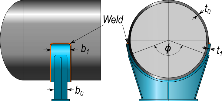
Derived methods therefore do take into account any applied wear or reinforcement plate. Depending on the opening angle ϕ and the plate width b1 of the saddle there are two common methods to take the additional thickness t1 of the wear plate into account.
Below the calculation of the maximum circular combined compression stress S3 according to Zick is briefly discussed. This is then compared with the compression stress as calculated with the derived methods. Finally the conditions under which each of these derived methods may be applied are examined.
Zick
In Zick's article [1] the maximum circular combined compression stress S3 occurs in the saddle's horn.
For L ≥ 8R the maximum circular combined compression stress S3 is calculated as follows :
(1) S3 =
| Q |
| 4tb2 |
| 3K3Q |
| 2t2 |
If L < 8R then S3 is :
(2) S3 =
| Q |
| 4tb2 |
| 12K3QR |
| Lt2 |
Here the first term of S3 in (1) and (2) describes the contribution of the membrane stress and the second term describes the contribution of the bending stress to the total combined compression stress.
In (1) and (2) b2 further represents the supporting length of the cylinder and is calculated as follows :
(3) b2 = b0 + 10t
| L | Length of the cylinder | mm |
| R | Radius of the cylinder | mm |
| t0 | Wall thickness of the cylinder | mm |
| b0 | Saddle width | mm |
| t1 | Wear or reinforcement plate thickness | mm |
| b1 | Wear or reinforcement plate width | mm |
| Q | Saddle load | N |
| K3 | Circumferential bending-moment constant | - |
| ϕ | Saddle angle | ° |
| b2 | Supporting length of the cylinder | mm |
| S3 | Combined circular compression stress at the horn of the saddle | N/mm² |
Method 1: Lineair summation
This method assumes that the saddle, plate and cylinder are connected by means of a weld. The load-bearing length b2 of the cylinder remains the same as with the Zick method, but the wall thickness t in (1) and (2) is replaced by t1 + t0 for both the bending stress and the compression stress term. Here t0 is the cylinder thickness and t1 is the thickness of the applied wear or reinforcement plate. The combined compression stress is now calculated as:
(4) S3,method1 =
| Q |
| 4(t0 + t1)b2 |
| 3K3 Q |
| 2(t0 + t1)2 |
| if L ≥ 8R |
Normally t0 ≤ t1 ≤ 1.5t0. Under the assumption that t1 = t0, as recommended in PD 5500 Annex G, it follows that t = 2t0 and consequently S3, method1 becomes :
(5) S3,method1 =
| Q |
| 8t0b2 |
| 3K3 Q |
| 8t02 |
| if t0=t1 and L ≥ 8R |
In (5) the denominators of both stress terms are greater than the corresponding terms in (1), so the total combined compression stress S3, method1 is significantly lower than S3 as calculated according to Zick.
Method 2: Sum of squares
This method is described in [2] and assumes that the cylinder and saddle plate work independently of each other. The load limits for bending in the cylinder and saddle plate are then each proportional to their squared thickness. One problem with this approach is that it does not take into account the deflection of the cylinder and the saddle plate.
Again the calculation of the supporting length b2 of the cylinder is as with the Zick method. The membrane stress term is calculated according to the substitution of method 1. However, for the bending stress term t2 not the square of the sum is substituted, but the sum of the squares. So not (t0 + t1)2, but (t02 + t12). The combined compression stress is now calculated as :
(6) S3,method2 =
| Q |
| 4(t0 + t1)b2 |
| 3K3Q |
| 2(t02 + t12) |
| if L ≥ 8R |
If t1 = t0 the combined stress S3,method2 becomes :
(7) S3,method2 =
| Q |
| 8t0b2 |
| 3K3Q |
| 4t02 |
| if t0=t1 and L ≥ 8R |
Also in (7) the denominator for both stress terms has increased compared to S3, so also S3,method2 is smaller than S3 in (1).
Comparison and applicability of Zick, Method 1, and Method 2
Under the assumption that L ≥ 8R and t1 = t0 it follows that :
(8) | S3,method1 | ≤ | S3,method2 | ≤ | S3 |
Method 1 thus gives the most advantageous results for the combined circular compression stresses S3 in the horn of the saddle. The same applies under the alternative condition that L < 8R as in (2).
Which method should/may be applied?
Walther Stikvoort investigated horizontal pressure vessels supported by saddles in [3] and found unexplained differences in the calculation of the circular bending stress at the horn of the saddle. He asked the relevant code committee of PD 5500 about this.
In answer to his questions the Code Committee replied that they are working on a new proposal for G.3.1.5.2 in which the calculations depend on whether or not the saddle plate has been welded to the cylinder.
They propose to use method 1 when the cylinder and the wear or reinforcement plate are connected by an uninterrupted weld. This method gives the most advantageous results for the combined circular compression stresses S3 in the horn of the saddle. This also conforms to the current standard as described in PD 5500 - G.3.1.5.2 [4].
As an extension to G.3.1.5.2, tthe committee further proposes to use Method 2 when the cylinder is not welded to the wear or reinforcement plate. Cylinder and saddle plate can then react independently to the saddle load. The stress limit for bending in the cylinder and the wear or reinforcement plate is then proportional to the square of the individual thicknesses t0 and t1.